Content:
- Introduction
- Technical Specifications
- Overview of BCInline
- Engineering Drawings
- Installation and Setup
- Control of the BCInline
- Cleaning and Maintenance
- Spare Parts
- Warranty
- Disposal and Recycling
Introduction:
Important Notes:
Important information that is not safety-related is shown in a note message like one of the following:
![]() This note gives information on how to avoid equipment malfunctions or property damage. If you do not follow this note, your warranty may be voided or you may receive incorrect measurements or both
This note gives information on how to avoid equipment malfunctions or property damage. If you do not follow this note, your warranty may be voided or you may receive incorrect measurements or both
![]() This note gives other useful, important information
This note gives other useful, important information
Intended Use:
The intended use of the BCInline is to measure the surface energy properties of a material surface. Do not use the BCInline for any other use.
The BCInline is not intended for use in hazardous locations. If you require a BCInline for use in hazardous locations, contact Brighton Science.
Contact Us:
Contact us for general inquiries, technical support, and sales:
Brighton Science
4914 Gray Road
Cincinnati, OH 45232
513.469.1800
Visit us at brighton-science.com
Brighton Science
Technical Specifications:
|
Item |
Specification |
|
Weight |
18 lb (8.2 kg) with full cartridge |
|
Control Cabinet Dimensions |
Height:12 in (300 mm) Width: 15 in (380 mm) Depth: 6.1 in (155 mm) |
|
Length of inspection head tether |
59 - 82 in (1.5 - 2.1 m) |
|
Control Cabinet Protection Class |
IP 54, NEMA 12 |
|
Power |
12 VDC, 2.5A Power supply (input): 100-240 VAC, 0.3A, 50/60 Hz Power supply (output): 12 VDC, 2000 mA Power supply cable length: 53 in (1346 mm) |
|
Operating conditions |
Indoor use only Maximum altitude: 6562 ft (2000 m) Temperature: 41° - 104°F (5° - 40°C) Minimum relative humidity:15% Maximum relative humidity: 80% for temperatures up to 31 °C (88 °F), decreasing linearly to 50% relative humidity at 40 °C (104 °F) |
|
Noise emission |
Less than 72 dB(A) |
|
Cartridge fluid |
HPLC-grade water (standard) |
|
Cartridge capacity |
10,000 measurements |
|
Cartridge weight (full) |
1.0 lb (450 g) |
|
Inspection time |
2 seconds * |
|
Image storage capacity |
40,000 |
*Inspection times may be longer with certain options enabled.
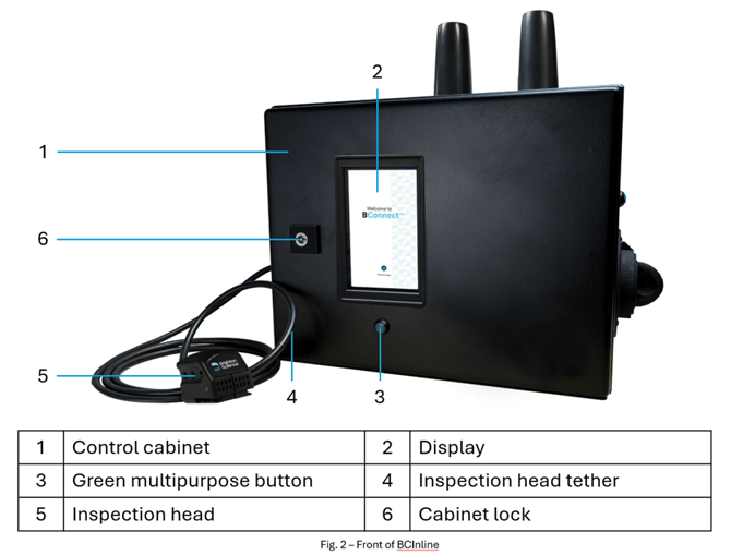
Overview of BCInline:
The BCInline is an inspection device that is designed to be integrated into your existing equipment. It determines surface energy by measuring the contact angle of a water drop deposited on your surface. The measuring, image processing, and results calculations are controlled by Archer, Brighton Science's proprietary software.
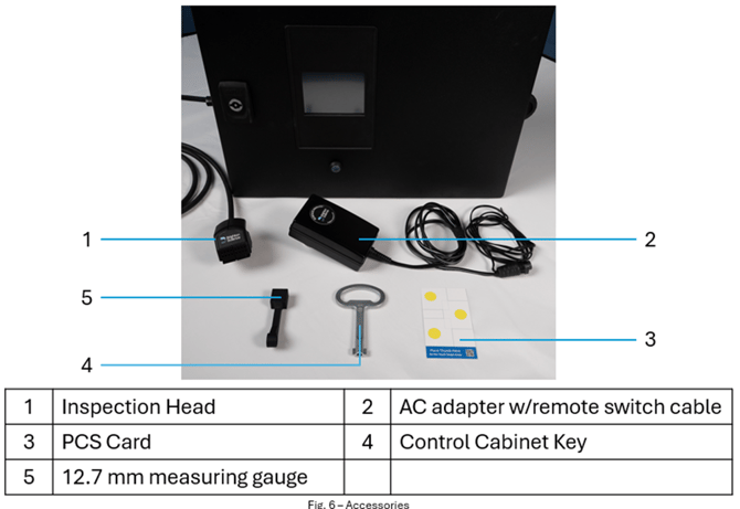
The main system components consist of the following:
- The BCInline control cabinet which houses the BConnect software, the fluid dispensing system, and associated controls
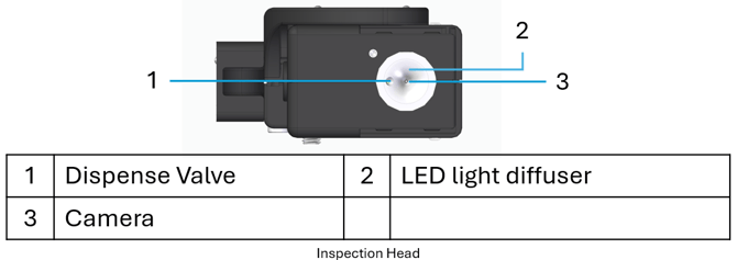
- The inspection head containing the camera, lights, and fluid dispensing nozzle
BCInline Diagrams:
Engineering Drawings:
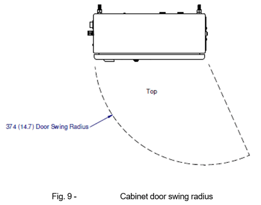
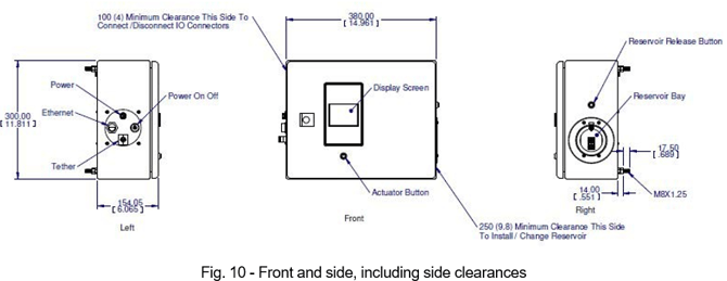
Control Cabinet:
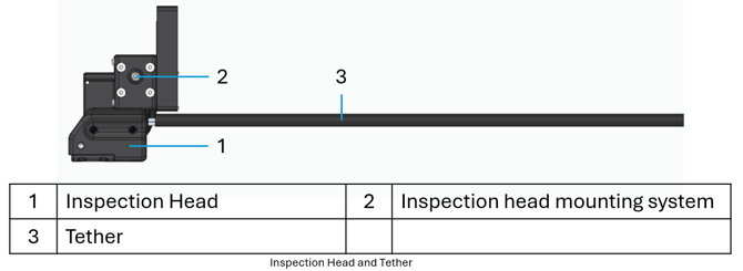
Inspection Head and Tether:
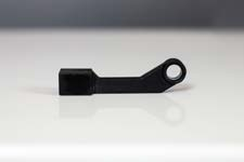
The BCInline measurement head mounting bracket and supporting options can be found in the link below:
BCInline Measurement head mounting options
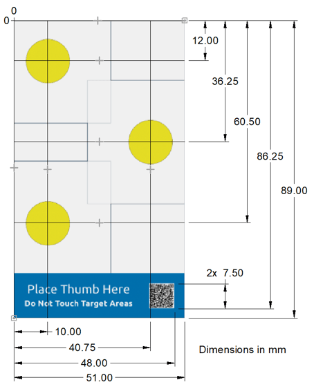
PCS Card:
Use this drawing of the PCS card for accurate programming of the performance check positions and the QR code.
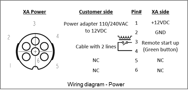
Wiring Diagram:
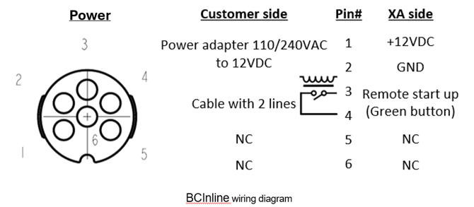
NOTE:
- an AC/DC adapter with connector is included with system
- If customer provides power via the connector, the device will accept 8-40 VDC.
Installation and Setup
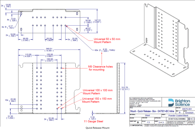
Mounting the Quick Release Bracket:
The BCInline system comes with a Quick Release Mounting bracket that should be used to mount the main control cabinet. This mounting system allows for the easy removal of the control cabinet when it needs to be exchanged for either service or calibration.
It is important to follow these guidelines when mounting the quick release bracket and control cabinet:
- Be sure to orient the control cabinet so that users/operators have access to and can change the fluid cartridge. Refer to "Control Cabinet" section above for clearance recommendations.
- The Control Cabinet shall be mounted such that the final measurement head (inspection location) position is within ±475 mm (1.5 ft) vertically (up or down) relative to the Control Cabinet mounting height. This requirement applies only to the final relative vertical position between the measurement head and the Control Cabinet and does not impose any restriction on cable routing or path.
- Never disconnect the inspection head tether from the control cabinet. Be sure to have a way of getting the inspection head inside your cell without detaching it.
- If possible is it ideal to have the Control Cabinet slightly above the measurement location(s)
-
- Ensure that this guideline is also followed when selecting a location for the Performance Check Surface measurements
- Ensure the display can be easily referenced and accessed by a user/operator
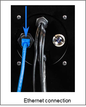
Connect the Ethernet Cable:
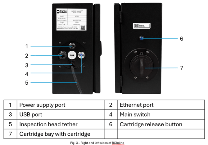
An Ethernet connection is required to interact with the remote API Control of the device. Connect an RJ45 Ethernet Cable(not included) to the port shown below (Ethernet connection).
Connect the Power:
Connect the AC adapter to the power supply port as shown in the figure below. Plug the AC adapter into a standard 120 VAC outlet.
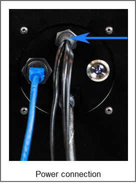
If you want to control the green multipurpose button remotely (for remote start-up, for example), wire a dry contact into the remote switch activation cable (pre-wired with the AC adapter). Close the contact for 0.5 seconds for remote start-up.
To start the BCInline manually, press and hold the green multipurpose button for 1 second.
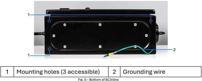
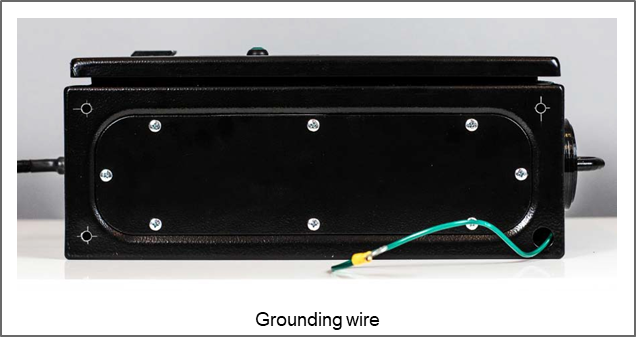
Grounding:
A grounding wire with an M6 ring terminal has been installed and is accessible through the bottom of the control cabinet.
Set up Communications:
Setting up communications is only required for Remote API Control. Refer to the Control API Guide for the following information:
- How to open a socket
- Baserecommendedsettings
- Testingcommunications
A router is included with the BCInline. Follow these setup instructions:
- ConnecttheBCInlineEthernetportwiththePCEthernetportusingastandardEthernet
- Open any browser and enter the default router IP address: 192.168.0.1
- Username is auto-populated with: "root".
- Enter the default password admin.
The router home screen appears as seen below:
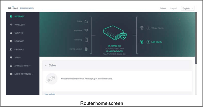
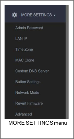
- In the left-hand menu, go to MORE SETTINGS to change settings as necessary.
- Select Admin Password to change the administrator password.
- Select LAN IP to change the default router LAN IP.
-
NOTE: Changing the default router LAN IP address will delete the BCInline fixed IP address!
-
- Select Advanced to change any router settings.
- To change the BCInline fixed IP address, do the following:
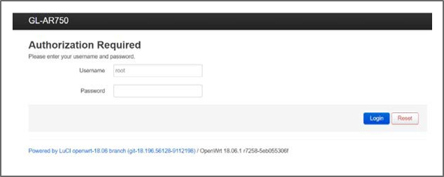
- Select MORE SETTINGS ⇒ Advanced
- You are prompted to enter your Use the default password (admin) or the new password, if you changed it.
-
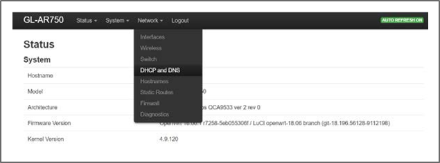
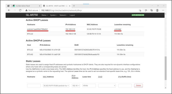
- Select Network ⇒ DHCP and DNS
-
- Scroll to the bottom of the page to the Static Leases The default IP address for the BCInline is set to 192.168.0.30.
 The BCInline must be bound to a static IP address
- Scroll to the bottom of the page to the Static Leases The default IP address for the BCInline is set to 192.168.0.30.
-
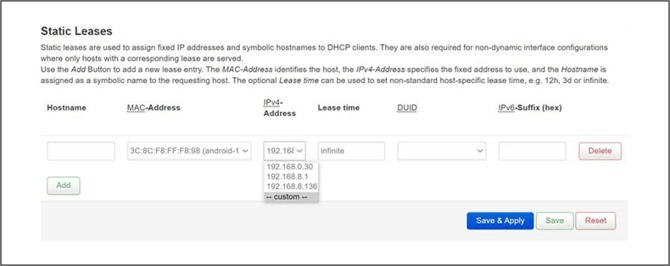
- Click the IPv4 Address pull-down menu. Select custom to set the new IP address within router’s LAN IP range
-
- Type in Infinite in the Lease time
- Click Save & Apply.
Mount and Position the Inspection Head:
- For service purposes, the inspection head must be detachable from the robot or XYZ axes to which it is mounted.
- When positioning the inspection head, be sure to observe the following:
- Head orientation must always be downwards for purging and performance checks.
- Do not excessively bend the tether. The bend radius of the tether should not be less than 84mm (3.3").
- Do not allow the tether to be compressed or crimped.
- Never disconnect the inspection head tether from the control cabinet. Be sure to have a way of getting the inspection head inside your cell without detaching it.
- For service purposes, the inspection head must be detachable from the robot arm or axes to which it is mounted.
- For best measurement results, avoid internal lighting within the cell, and protect the inspection head from exposure to external light sources during Light sources other than the light emitted by the inspection head can negatively affect the drop detection.
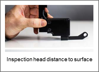
- The distance of the measurement head to the surface to be measured must be 12.7mm. Use the provided 12.7mm Measurement Gauge to ensure appropriate distance when setting up measurement locations.
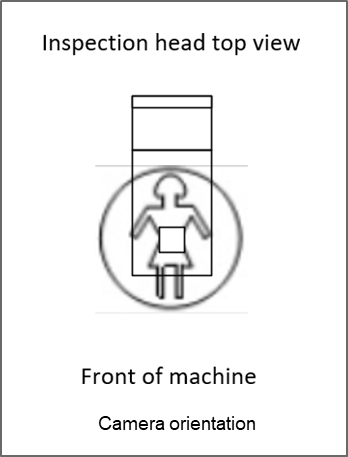
- The orientation of the camera on the inspection head mounting plate is as shown in image below.
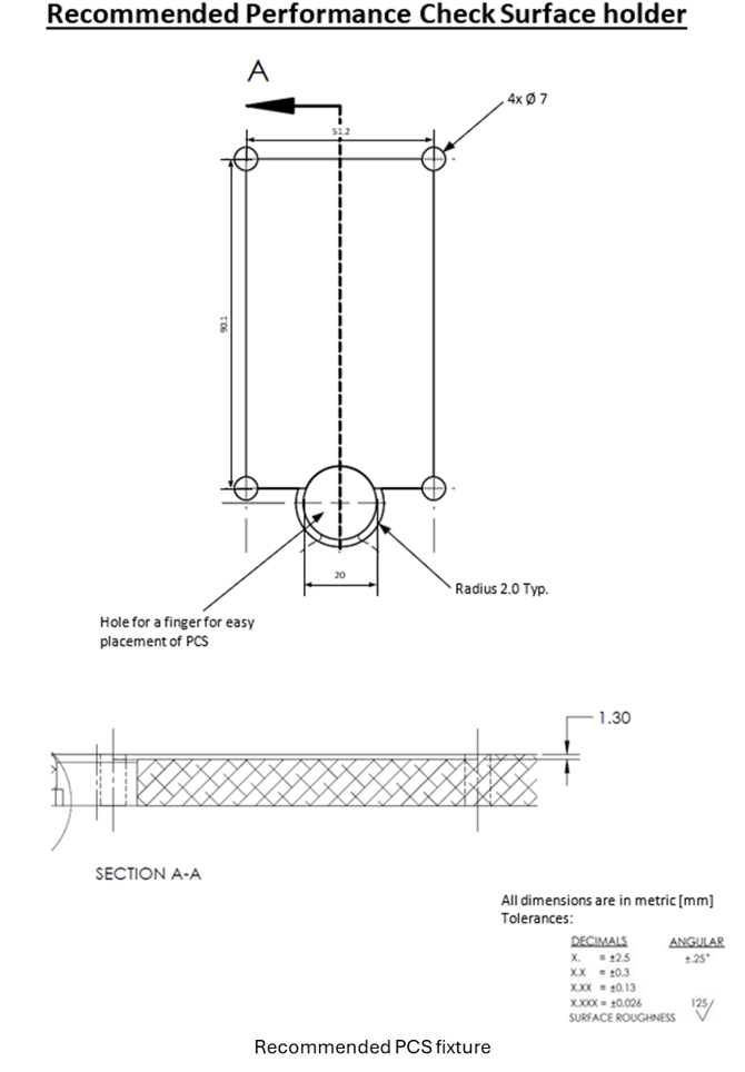
Set up a PCS Fixture:
A PCS (Performance Check Surface) is a special card used for performance checks (see "Performance Checks").
It is recommended that you make a fixture to hold the PCS card like the design shown below. For a drawing of the PCS card, see PCS Card above.
![]() Be sure to position the PCS fixture so that it is accessible to the user and ideally at a similar height to the product/parts to be measured.
Be sure to position the PCS fixture so that it is accessible to the user and ideally at a similar height to the product/parts to be measured.
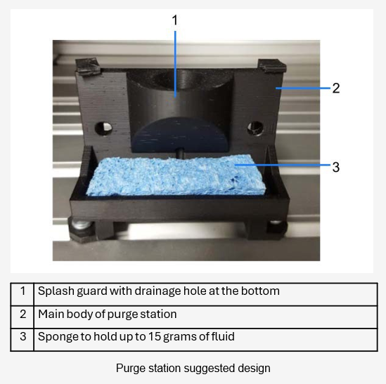
Set Up a Purge Station:
An appropriate receptacle (purge station) should be provided to absorb the fluid that is released from the inspection head nozzle during a prime or purge. An example of a suggested purge station design is shown below.
Control of the BCInline
This section gives information on how to control the various functions of the BCInline. For information regarding how the BCInline works, refer to the BCMobile user manual.
The functionality of the hand held device shoulder buttons is the same as the green multipurpose button on the control cabinet of the BCInline
![]()
For systems configured with Remote API Control: While most functions will work with robot mode on, turn robot mode off for full functionality of the touchscreen and pop up messages. To turn robot mode off, use the RD command RobotModeOff> followed by a system reboot. Turn robot mode back on with the command RobotModeOn> followed by a system reboot.
Remote API Control (Full Control):
Remote API Control is the standard method of controlling the BCInline whereby remote device commands (RD commands) are issued over an Ethernet connection. Further information, as well as a detailed description of all RD commands, can be found in the Control API Guide.
The operations described in this section are as follows:
- Startup --Performed every time the BCInline is turned on
- Measurement runs--The normal production measuring process
- Performance check--Performed periodically to maintain optimal performance of the BCInline
- Cartridge change--Performed whenever the fluid cartridge is empty and needs changing
- Purging--Performed when air needs to be expelled from the tubing
- Data Management--Clearing the database storage before it is full
- Shutdown--Performed when the BCInline is turned off
- Other functions--live video
![]() Because no unsolicited messages appear during operation, periodically check the status to verify connectivity and to look for issues. Use the RD command GetStatus> to verify connectivity and to retrieve the following information:
Because no unsolicited messages appear during operation, periodically check the status to verify connectivity and to look for issues. Use the RD command GetStatus> to verify connectivity and to retrieve the following information:
-
- Free storage space available
- Cartridge status
- Performance check status
- Pump status
Startup:
The startup sequence needs to be performed every time the BCInline needs to be turned on.
- Press the main switch to connect the BCInline controller to power
- Power on the BCInline using one of the following methods:
- Press and hold the green multipurpose button for one second to power on manually.
- Power on remotely if you wired in a dry contact into the remote switch activation (See "Connect the Power" above.)
- The startup sequence takes about 2-3 minutes. During startup, the Ethernet connection starts working. To check if the BCInline is up and running, you can send a ping (RD Command Ping>) periodically (every 10 sec is recommended).
- After the startup sequence is complete, the BCInline goes automatically to the Measurement
- Send RD Command GetStatus> to verify the following:
- Free Space is > 20%
- Cartridge status = CART_OK
- Performance Check status = PCHECK_OK
- Pump status = PUMP_OK
- Send RD Command DropCount> to check if there are enough drops for your run. It is recommended to display the amount of available water on the user interface.
 The BCInline will stop measuring when the device runs out of water. Make sure you have an adequate number of drops to complete your batch prior to starting a run.
- Send RD Command GoToMeasurement> to make sure the system is still in measurement mode.
- Move the inspection head to the purge
- Perform a TenShot purge
- The Ten Shot purge is performed every time the BCInline is turned on and anytime it has not been used for more than 2 hours.
-
RD Command: TenShotPurge>
-
The TenShot purge takes about 7 seconds to complete.
Measurement Runs:
When taking a measurement, the BCInline deposits a drop on the surface to be measured, takes a picture of the drop deposition, processes the image, and then returns the results. Do the following steps for each measurement run.
- Activate measurement mode to start the pump and prepare the BCInline for RD Command: GoToMeasurement>
- Move the inspection head to the purge station, if priming is to be performed.
- Prime the BCInline. Priming fills the nozzle with water and prepares the valve for dispensing. This is necessary because the water in the valve can evaporate over time. A prime shot only needs to be performed if the BCInline has not taken a measurement in the past 10 minutes.
-
RD Command: PrimeShot>
-
- Load a surface profile. A surface profile is a group of settings for the particular surface you are measuring. You do not need to load a new surface profile if you are continuing to measure the same surface as the previous measurement.
- Display available surface profiles: GetProfiles>
- Load surface profile "a": LoadProfile(a)>
- Move the BCInline inspection head to the location where the measurement will take place. Make sure the inspection head is 12.7 mm over the surface (see "Mount and Position the Inspection Head" ).
- Take a measurement.
- RD Commands:
- To take a measurement which includes the picture image, use Measure>.
- To take a measurement with no picture image, use MeasureNP>.
- RD Commands:
![]() For information about the results packets returned by the BCInline, refer to the Control API Guide.
For information about the results packets returned by the BCInline, refer to the Control API Guide.
- Check for errors. For example, if you move the inspection head fast and stop hard, you most likely will get the error TM_ERROR-PRESSURE-XXX>. This is because of movements of the waterline require the pressure to stabilize. If you receive the pressure error, send the Measure> or MeasureNP> again for up to 10 times.
- Repeat preceding steps for each measurement of the run.
Performance Checks:
A performance check is recommended at the beginning of each day and as needed to verify that the BCInline is operating at maximum performance.
Use the following RD commands to verify when the last performance check was completed:
- For the date and time of the last performance check, use GetLastPCHK>.
PCS Card Recommendations:
Follow these recommendations for best results
- Only deposit a single measurement on each target of the PCS card.
- Make sure that the PCS cards are held flat at all times during a performance check.
- Change out the PCS card after the completion of a performance check.
- Be aware that the position of the yellow circles can vary due to tolerances of the card and holder. It is best not to measure too close to the edge of the circle.
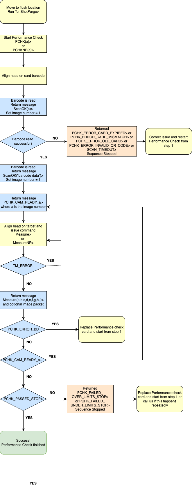
Performance Check Sequence:
The PCHK(a)> command is used to initiate a performance check, where "a" is the timeout in seconds. Each measurement within the sequence uses Measure> or MeasureNP> commands. Refer to the Control API Guide for more detailed descriptions of these commands.
Cartridge Change:
When the fluid cartridge is empty, it needs to be changed. Check the fluid remaining in the cartridge with the following commands:
- RD Command: DropCount>
- BCInline will return the information in the form (a,b) where:
- a = number of drops used
- b = number of drops available
- BCInline will return the information in the form (a,b) where:
Follow these steps to change a fluid cartridge:
- Move the BCInline inspection head to the purge station.
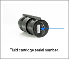
- Use the RD command ChangeCartridge(a)> to begin the cartridge change, where "a" is the 16- character serial number located on the new cartridge. You can enter the dashes or omit them.
- The BCInline responds with CC_SERIAL_OK> if a valid code was entered.
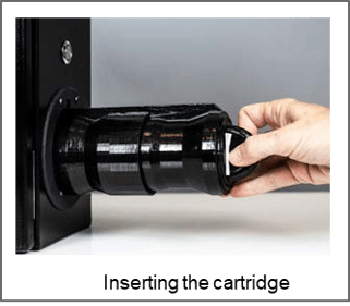
- The following message appears on the touchscreen: "Please remove the old cartridge by pressing the release button and pressing forward to unlock it". Remove the cartridge by pushing down on it while pressing the release button as shown below.

- After removing the cartridge, the message is displayed: "Please insert the cartridge with serial number x", where "x" = the serial number you entered for the new cartridge.
- Insert the new cartridge, pushing it in until it clicks into place.
- The BCInline begins a continuous See "Purging" below for more information. The message "Purging..." appears on the touchscreen.
- When the cartridge change sequence is complete, the BCInline returns the message CC_COMPLETE>.
- Send the used cartridge back to Brighton Science.
![]() Avoid removing a fluid cartridge unnecessarily. Every time a cartridge is re-installed, the BCInline performs a continuous purge.
Avoid removing a fluid cartridge unnecessarily. Every time a cartridge is re-installed, the BCInline performs a continuous purge.
Purging:
Purging pushes fluid through the tubing to ensure consistent dispensing. Purging is also used to force air out of the tubing after activities such as cartridge changes, inspection head changes, and troubleshooting.
Purging should be performed with the inspection head positioned over the purge station to contain the fluid that is released.
The types of purging operations include the following:
- Ten shot purge
- RD Command: TenShotPurge>
- Uses 10 drops
- Performed whenever the BCInline is turned on
- Performed whenever the BCInline has not been used for more than 2 hours
- Takes 7 seconds to complete
- RD Command: ContinuousPurge>
- Uses 100 drops
- Long duration
- Performed after a cartridge change
- Performed automatically in certain cases during a performance check
- Takes about 8 seconds to complete Continuous purge
Shutdown:
- Use the RD command ShutDown> to power down the
- Press the main switch to turn off the power
![]() If you are finished with a measurement run, but you decide not to shut down the BCInline, you should turn the pump off using the command PumpOff>. You can turn the pump back on with the command PumpOn> or GoToMeasurement>.
If you are finished with a measurement run, but you decide not to shut down the BCInline, you should turn the pump off using the command PumpOff>. You can turn the pump back on with the command PumpOn> or GoToMeasurement>.
Other Functions:
The following table describes other common functions you can perform with RD commands. For more detailed descriptions as well as a complete listing of all RD commands, refer to the Control API Guide.
|
Function description |
RD Command |
|
Display the current image of the BCInline screen. You can create a live video stream for setup and user alignment by the repeated use of this command. |
GetScreen> |
Cleaning and Maintenance
Proper cleaning and maintenance is important to keeping the BCInline functioning at peak performance.
Keeping the BCInline Clean
Do the following to keep the BCInline clean:
- Use LCD display wipes to clean the touchscreen.
- Wipe the control cabinet with a slightly damp cloth.
- Isopropyl alcohol (IPA) may be used to clean the bottom of the inspection attachment.
![]() Never use cleaners that contain ammonia. Never use any abrasive chemicals, solvents or soaps.
Never use cleaners that contain ammonia. Never use any abrasive chemicals, solvents or soaps.
Maintaining the BCInline
Do the following maintenance to keep the BCInline functioning properly:
- It is recommended to have the BCInline calibrated every A message appears on the screen when you log in if the unit is due for calibration. Contact Brighton Science to have your equipment calibrated.
 Failure to have your BCInline calibrated may result in unreliable contact angle measurements
- Handle the inspection head with care.
 Do not try to remove the camera, lights, fan filter, or any other part.
 Never insert anything into the nozzle or valve orifice, as you may damage it. If the valve becomes clogged, contact Brighton Science.
Spare Parts
The following items are available for purchase. Contact Brighton Science Sales Department at (513) 469- 1800, or orders@brighton-science.com. You can order online at brighton-science.com
|
Item |
Part Number |
|
|
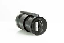
XA Fluid Cartridge (Water) |
|
30104 |
|
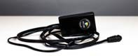
AC Adapter with remote switch activation cable (US version) |
|
30124-000 |
|
AC Adapter with remote switch activation cable (International version) |
|
30124-001 |
|
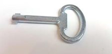
Control cabinet key |
|
11656 |
|
12.7 mm measuring gauge |
|
11657 |
|
USB Drive |
|
11234 |
|
Performance Check Surface (PCS cards) - 3 target Pack of 25
|
|
12323-001 |


Warranty
- Reference PO acknowledgement for Terms and Warranty information
- This manual is provided for informational purposes only and does not form part of any contract or warranty.
Disposal and Recycling

This symbol on the product(s) and / or accompanying documents means that used electrical and electronic products should not be mixed with general household waste. For proper treatment, recovery and recycling, please take this product(s) to designated collection points where it will be accepted free of charge.
Alternatively, in some countries you may be able to return your products to your local retailer upon purchase of an equivalent new product.
Disposing of this product correctly will help save valuable resources and prevent any potential negative effects on human health and the environment, which could otherwise arise from inappropriate waste handling.
Please contact your local authority for further details of your nearest designated collection point.
Penalties may be applicable for incorrect disposal of this waste, in accordance with your national legislation.
For business users in the European Union:
If you wish to discard electrical and electronic equipment, please contact your dealer or supplier for further information.
Information on Disposal in other Countries outside the European Union:
This symbol is only valid in the European Union. If you wish to discard this product, please contact your local authorities or dealer and ask for the correct method of disposal.
Do not dispose of batteries in the trash or in a single stream recycling program. Take all unneeded, spent, or damaged batteries to a facility that specifically handles lithium-ion battery disposal.